Downloading and opening Simulink projects in MATLAB R2017b
1. Line follower project
First project that I have tested in Simulink was The Line follower project. It is a model of a small robot, that is supposed to follow a line drawn on the floor.
As can be seen on the following image, the project is divided into several directories, plus there is the LineFollower.prj file which is very important, because is should be used as a key for opening the project. Simply open this file in MATLAB and automatic scripts and MATLAB compilator will do the rest for you.
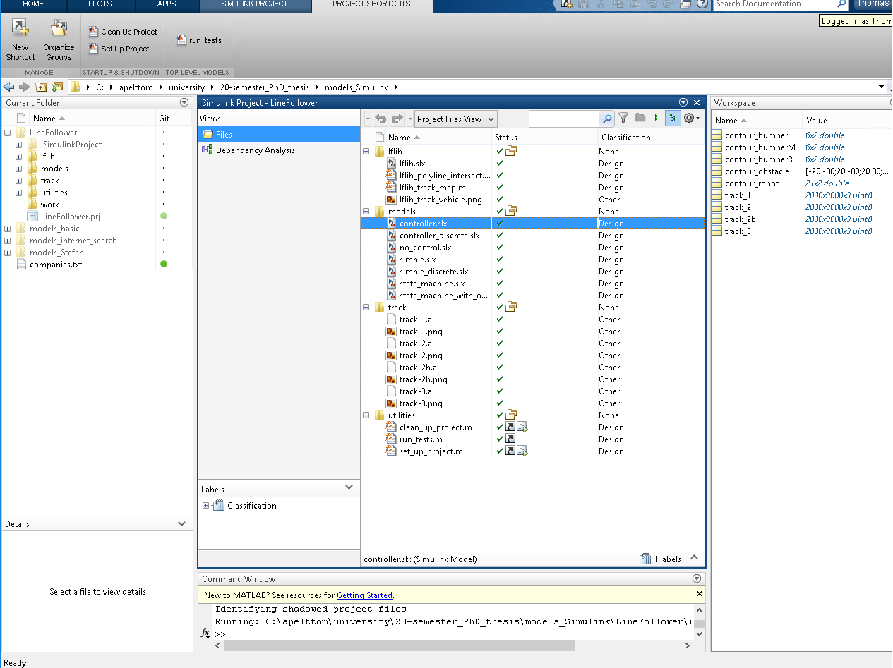
Under utilities folder there are MATLAB scripts which set up and clean the project + test script. Folder track contains data of the particular tracks + their images (images load to the simulation so it seems that the robot is going around the track. Folder flib contains definition of a S-function block. TODO: need more information!
- S-function block An S-function is a computer language description of a Simulink block written in MATLAB®, C, C++, or Fortran. C, C++, and Fortran S-functions are compiled as MEX files. S-functions follow a general form and can accommodate continuous, discrete, and hybrid systems. By following a set of simple rules, we can implement an algorithm in an S-function and use the S-Function block to add it to a Simulink model. They are practically blocks of your own funcionalitty which can do whatever you design them to do. After you write your S-function and place its name in an S-Function block (available in the User-Defined Functions block library), you can customize the user interface using masking.
- Masking is very useful because it makes model appear more real for other engineers. Without masking, models are only spagetti net of basic Simulink mathematical blocks and user defined components but masking helps us to wrap logical units (such as DC motor, robot plant, adapter, converter, engine, control unit, etc.) into atomic Simulink blocks. If we would like we can even add pictures and schematics! See this tutorial.
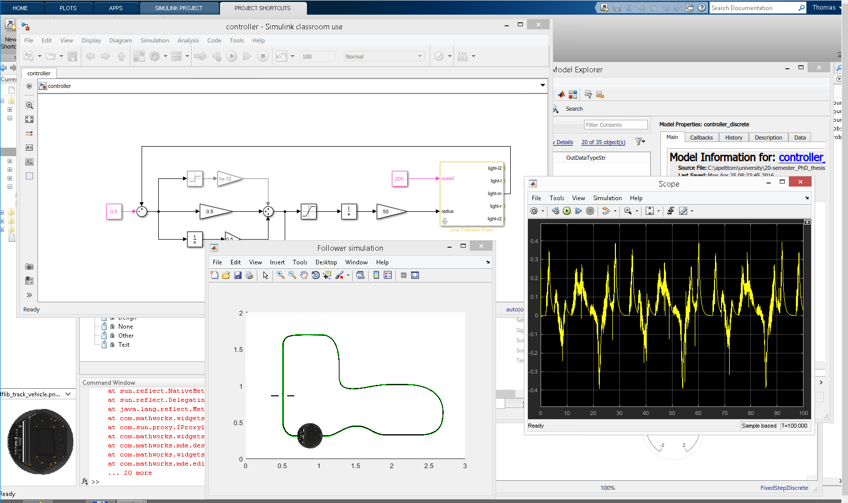
- controller.slx is a definition of a logic, which controls robot plant on the track. Uses only one signal from the plant as input (feedback). This is done by Simulink basic blocks (constants, sums, integrator, math function, etc.). This model is of course runnable, we can start a simulation if we specify step size (or we can set it to auto and Simulink will use ode45 solver and sets step size to 0.01).
- controller_discrete.slx is slightly different. It has different discrete time integrator function and there is rate Rate Transition block in addition. Still it uses only 1 signal from the plant as input to the controller. It uses FixedStepDiscrete solver, whatever it is.
- no_control.slx presents a case when the robot is not being controlled. It doesn't use any of the signals from the plant as input. The only command, which is given to the plant of the robot is constant speed 200 units (so the robot will just run forward until it will crash, start burning and evantually explodes).
- simple.slx is only simple feedback control. Uses 2 signals as a feedback from the plant (medium and right sensor). It seems that it can go forward, backwards and stop. There are two simple switches for sending signal of 100 units, -100 units or 0 units into the robot plant. If we run the simulation, robot moves few units, passes finish line and stops.
- simple_discrete.slx is a variation of the model mentioned above, but with FixedStepDiscrete solver. It also possesses Rate Transition (TODO research deeper) which somehow transfer data between signal sent and plant input port. If we run the simulation, robot is able to follow the line.
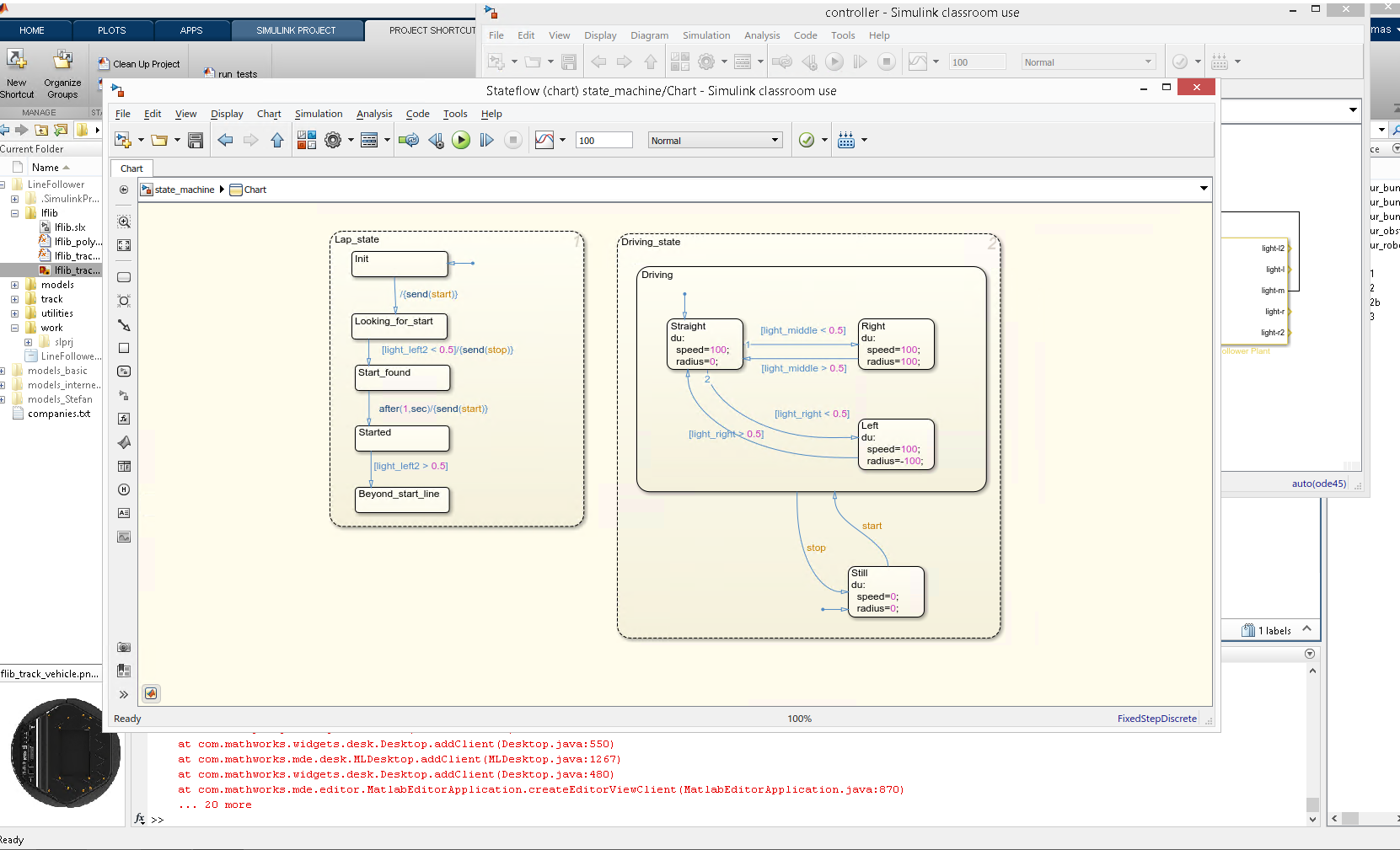
- state_machine.slx is a controller build using Stateflow package and opposite to all previous models it actually uses all the signals, coming out from the robot sensors. All of them are wired as inputs into the state machine which has only two outputs (used to control the robot) and these are speed and radius. The state machine is very simple, yet powerful.
- state_machine_with_obstacle.slx is even more powerfull and model a controller which receives signals not only from the sensors on the front of the robot, but also from the bumbers and wheels, making robot able to hit obstacles and possibly go around them.
Now we have pretty good idea about Simulink project and it's models. We should link our knowledge into S-Taliro world. Task list:
- Study documentation for LineFollower
- Create MTL specification for LineFollower
- Run S-Taliro tools on the example